Using the Main Window
- Overview
- Concepts
- Quick Start
- Description
- The Main Menu - Access useful features
- The Project Tree - Navigate through projects and modules
- Database Nodes - Configure BinNavi databases
- Projects Nodes - Get an overview of the projects in a database
- Project Nodes - Work with a single project
- Address Space Nodes - Work with a single address space
- Modules Nodes - Get an overview of the modules in a database
- Module Nodes - Work with a single module
- Native Callgraph Nodes - Work with the callgraph of a module
- Native Flowgraph Nodes - Work with the flowgraphs of a module
- Function Nodes - Filter module functions by their type
- Module Views Nodes - Work with the user-created views of a module
- Project Views Nodes - Work with the user-created views of a project
- Callgraph Views Nodes, Flowgraph Views Nodes, Mixed Graph Views Nodes - Filter user-created views by type
- Tagged Views Nodes - Filter views by their tags
- Node-Tagged Views Nodes - Filter views by the tags of their nodes
- Trace Nodes - View previously recorded debug traces
- Data Nodes - View the binary data of the input file
- Global Variables - View the global variables of a module
- Debuggers Nodes - Get an overview of the pre-configured debuggers
- Debugger Nodes - Configure individual debuggers
- View Tags Nodes - Get an overview of the existing view tags
- View Tag Nodes - Modify a single view tag
- Hotkeys
Overview
The main window of BinNavi gives you quick access to all data in your BinNavi databases. You can browse through disassembled modules, combine multiple modules into address spaces and projects, or configure the debuggers you want to use. Read on and find out how to use these and other features of the main window.
The main window is divided into two parts. The left half contains the so called Project Tree that gives you access to all configured BinNavi databases and their content. Among other things, this tree allows you to quickly navigate to all the projects and modules you have already added to the database during previous work sessions. The right half of the main window changes depending on what is selected in the Project Tree. Here you can find additional information and features that are useful in the context of the currently selected object.
Concepts
- Project Tree: The Project Tree is shown on the left side of the main window. Here you can see the previously configured BinNavi databases and their content. The Project Tree is the primary way of navigating through all the imported modules, their disassembled data, and other things like the available debuggers or the configured view tags.
- Database: BinNavi uses a PostgreSQL database to store all data. Many of our customers found it useful to work with more than one database at the same time so we made it possible to configure and work with as many databases as you want to.
- Module: A module represents a single disassembled file.
- Project: Sometimes working with a single module is not enough. To analyze the interaction between two or more modules (think of an executable and its dynamically loaded libraries), it is necessary to create a project and add all required modules to it. Inside projects, sets of modules are treated and analyzed just like a single module.
- Address Space: In projects you can define one or more address spaces. Each address space represents the virtual memory of a process on a real machine. Modules can be added to an address space to simulate the address space of a real process, for example a running executable and all of its dynamically loaded libraries.
- View: A view is any kind of graph that is shown end edited in the graph window. Typically you start analyzing the control flow graphs of functions in the module you are working with. Later on you can create your own graphs to do more advanced analysis.
- Native View: A native view is a view that is based on the original data of a disassembled file. BinNavi creates one native view for each function of a module and one additional call graph view that shows the call graph of the module. Native views can not be modified.
- Non-Native View: A non-native view is a user-defined view that represents an arbitrary part of a module. For advanced analysis you can create non-native views with the help of BinNavi standard functionality or with your own scripts and plugins. Unlike native views, non-native views can be modified.
- Flow graph View: A flow graph view is a view that contains only basic blocks. All native function views and many non-native views are flow graph views.
- Call graph View: A call graph view is a view where each node represents a function and each edge shows how one function calls another function. The original call graph of a module is an example of a call graph view. It is also possible to create non-native call graph views, for example when it is necessary to cut down a huge native call graph to a smaller, more manageable call graph view.
- Mixed View: A mixed view contains both basic blocks (like a flow graph view) and function nodes (like a call graph view). Mixed views are always non-native views that are created during advanced code analysis.
- Tagged View: A tagged view is a view that was assigned one or more view tags. View tagging helps you find views you previously marked as interesting.
- View Tag: A view tag is a simple descriptor that can be assigned to any kind of view. Using view tags it is possible to mark views as "already analyzed", "interesting", or any kind of user-defined view tag.
- Module View: A module view is a view that belongs to a module. It can only contain elements (nodes, instructions, comments, ...) that from the module.
- Project View: A project view is a view that belongs to a project. A project view can contain elements (nodes, instructions, comments, ...) from all modules in the project.
- Normal Function: A normal function is a function that has no special properties (i.e. it is not one of the other function types).
- Library Function: A library function is a function that belongs to a library that was statically linked to a module. Common examples for this kind of function are the functions of the C standard library.
- Imported Function: An imported function is a dynamically linked function. These functions are not actually present in the module but in a dynamically linked library.
- Thunk Function: A thunk function is a small function that contains just a single jump instruction to an imported function.
- Thunk Adjustor Function: A thunk adjustor functions are used for C++ multiple inheritance, by certain compilers, to solve the vtable layout issue.
- Unknown Function: If a BinNavi exporter can not determine the type of a function, the function type defaults to Unknown.
- Debugger: It is possible to configure debuggers that can be used to debug modules and projects. Each pre-configured debugger can be used to debug many different modules and projects.
Quick Start
Q: What do I do in the main window?
A: When BinNavi is started for the first time, a new database
called Click and configure me is shown in
the Project Tree. You can set up the connection to your PostgreSQL database
there. Afterwards you can
import files into BinNavi and start to analyze them.
You may also want to check out the interactive tutorials which you can find in the Help menu of the main window. These tutorials help you become familiar with the most important aspects and features of BinNavi.
Q: How do I add a new Database?
A: You can either use the menu BinNavi -> Add
Database or you can right-click on the project tree and choose
the Add Database menu in the context menu.
Q: How do I import data?
A: To import data it is necessary to use one of the BinNavi
exporters. You can use the IDA exporter from
the BinNavi main window. To do so, right-click on a
Database node or a Modules node in the project tree
and choose Import IDB File in the context
menu. Once the import is complete, a new module that represents the
imported data shows up in the project tree.
Q: How do I create a project?
A: You can create a project by right-clicking on the Projects node in
the project tree and choosing the Create Project menu.
Q: How do I add a module to an address space?
A: To add a module to an address space you drag the module node
of the module onto an address space node.
Q: How do I tag a view?
A: To tag a view you have to create a tag first by right-clicking on the
View Tags node and choosing
Create Root Tag. Once the tag exists you can
drag a view from the views table on the right side of the main window
onto the tag node in the project tree.
Description
The Main Menu
The main menu on top of the main window can be used to access most functions available in the main window. Most of the main menu is static but the second menu option changes depending on what you have selected in the Project Tree.
The following options are always available in the main menu:
- BinNavi/Add Database: Adds a new database node to the Project Tree. A new BinNavi database can be configured at this node.
- BinNavi/Exit: Exits BinNavi
- Module/Import IDB file: Opens the import a module dialog.
- Module/Refresh: Refreshes the modules currently known to BinNavi.
- Module/Resolve all imported functions: Tries to resolve the imported functions to other modules in the database.
- Module/Sort: Sorts the modules either by name or by creation date.
- Plugins/Open new Scripting dialog: Opens the scripting dialog of the main window. You can write simple scripts that access the BinNavi there.
- Plugins/Open log window: Opens the scripting log window where you can read the log output produced by all scripts and plugins.
- Plugins/Plugin Manager: Shows the plugin manager dialog. You can configure what plugins should be loaded and in which order they should be loaded here.
- Plugins/Reload Plugins: Reloads all plugins. This is useful when you are developing new plugins and you want to test changes you have made to your code.
- Plugins: All plugins that should be accessible from the main menu can add their menus here.
- Settings/Settings: Shows a dialog where you can configure global BinNavi options.
- Settings/Initial Callgraph Settings: Shows a dialog where you can configure settings that are used when a native call graph view is first shown.
- Settings/Initial Flowgraph Settings: Shows a dialog where you can configure settings that are used when a native flow graph view is first shown.
- Help/Manual: Opens the BinNavi manual in the default web browser.
- Help/Context Help: Activates context-sensitive help. In this mode you can click on GUI elements to pop up a dialog that shows you the purpose of the clicked elements. Press the right mouse button to leave context-sensitive help mode.
- Help/Tutorials: Gives you the option to select and work through an interactive BinNavi tutorial.
- Help/Report a Bug: Opens the BinNavi bug tracking website where you can report bugs.
- Help/About: Shows information about BinNavi.
The Project Tree
The Project Tree is the name of the static left-hand side of the main window. It gives you access to all configured BinNavi databases and most of the objects stored in them. Depending on the state of each database and what objects are loaded, the appearance of the Project Tree changes.
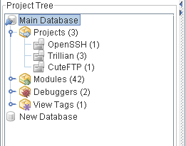
The screenshot above shows a partially expanded project tree with two configured databases (Main Database and New Database). The Main Database is loaded and contains three projects (OpenSSH, Trillian, and CuteFTP).
Once a database is loaded, you can navigate the Project Tree to explore its content. Depending on what node of the Project Tree is selected, the right side of the Main Window changes to provide more information about the selected node and the operations you can execute on it.
Most nodes of the project tree have a context menu that pops up when you right-click on the node. The same options are also available through the main menu when the node is selected.
Database Nodes
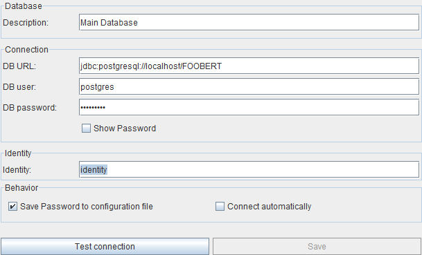
The database nodes are the top-most nodes of the Project Tree. Each database node represents a BinNavi database. When you select a database node, a panel to configure the database connection is shown on the right side of the main window.
-
Description: A name that identifies the database. This name helps you to identify a database when you have many databases configured.
-
URL: A URL that identifies the location of the PostgreSQL database. You can configure the location of the database server, the database server port (if it is not listening on the default port 5432), and the name of the database name on the server.
-
User: The user that is used to log in to the database. Please make sure that the database user has sufficient database access rights. BinNavi requires the user to be able to create tables, to insert data into tables, and to delete data from tables.
-
Password: The password of the user that is used to log in to the database.
-
Show Password: If checked, the password in the password field is shown in plain text.
-
Save Password: If checked, the database password is stored in the BinNavi configuration file on your local hard drive. The password is stored in plain text.
-
Connect automatically: If checked, a connection to the database is established automatically when BinNavi starts. Otherwise you have to connect to this database manually.
-
Identity: The identity field is used for the BinNavi multi user features and identifies a single user by the string provided. It is essentially a nick name. Be aware that the multi user feature in BinNavi does not provide any security. This is due to the fact that everyone works on the same database and access should be restricted on this level not on the application level.
You can use the Test Connection button to find out whether BinNavi can connect to the database using the connection information from the database configuration panel. If the configured database does not yet exist, BinNavi offers to create it for you.
When you are done configuring the database, you can click on the Save button to store the database information in the BinNavi configuration file. This is necessary before you can load the content of the database.
When you select a database node, the following menu items are added to the main menu:
-
Connect to Database: Establishes a connection to the database.
-
Disconnect from Database: Closes an established database connection.
-
Import IDB file: Uses IDA Pro to import an IDB file to the database. This is functionally equivalent to the Import IDB file menu that is shown in the context menu of Modules nodes.
-
Remove Database: Removes the database configuration from BinNavi. The content of the database is not deleted from the PostgreSQL server.
These menu items are also available in the context menu of a database node that is shown when you right-click on a database node.
Projects Nodes
Projects Nodes provide an overview of the BinNavi projects stored in a BinNavi database. Each Projects Node says how many projects are stored in the database.
When you right-click on a Projects Node, a context menu with the following menu items is shown:
- Create Project: Creates a new project in the database.
When you select a Projects Node a table that gives basic information about all projects is shown on the right side of the main window.
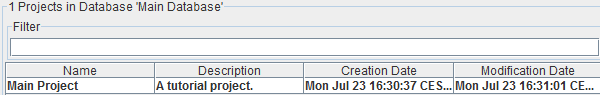
For each project in a database, the name, description and the number of views of the project is shown as well as the date when the project was created and the date when the project was last modified.
You can modify the name and the description of a project in the table by double-clicking on the corresponding field. If a field is already selected, you can simply start typing the new name or the new description.
You can filter the entries of the table by name or by description through entering text in the filter field. Only projects whose names or descriptions contain your search string are shown.
When you right-click on the table, a context menu provides the following options.
- Load Project: Loads all information about the project and the address spaces and modules inside the project. This option is only available if the project has not yet been loaded.
- Search View: Shows a dialog you can use to search for views inside the project. This option is only available if exactly one project is selected in the table.
- Add Address Space: Adds an address space to the selected project. This option is only available if exactly one project is selected in the table.
- Delete Project: Deletes the selected projects from the database.
- Search: Shows a dialog that helps you search for a string in the table.
- Copy Selection: Copies the content of the selected rows to the clipboard.
Project Nodes
Project Nodes represent BinNavi projects that contain one or more disassembled files. Their child nodes provide information about the address spaces and views of the project. The number shown in a Project Node tells you how many address spaces are part of the project.
When you right-click on a Project Node a context menu with the same project options as the context menu of the Projects Nodes table is shown. Only table-specific options are omitted.
When you select a Project Node more detailed information about the project is shown on the right side of the main window.
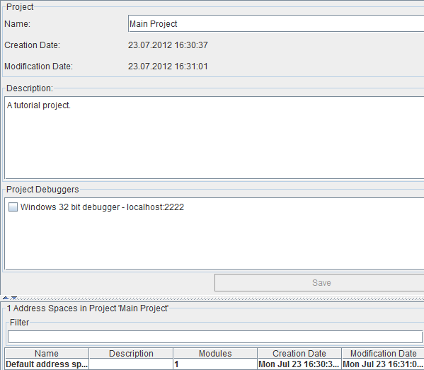
You can edit the following aspects of the project in the project information panel:
- Name: The name of the project. This helps you identify the project when you have many projects in your database.
- Description: Use this field to store a longer description of the project.
- Project Debuggers: You can use the project debuggers list to select the debuggers you want to use to debug the modules inside this project. The list contains all pre-configured debuggers known to BinNavi. If you check a checkbox next to a debugger, this debugger is made available for debugging the project.
Note that changes to the project name, the project description, and the project debuggers are not saved automatically. To save the changes, you must click on the Save button.
The lower part of the project information panel contains a table with information about the address spaces of the project. The names and descriptions of all address space are shown in the table as well as the number of modules inside the address spaces, the dates when the address spaces were first created and when they were last modified.
You can modify the name and the description of each address space in the table by double-clicking on the corresponding field. If that field is already selected, you can just start typing the new name or the new description.
You can filter the address spaces table by name or by description. Additional filtering strings are available in the context menu of the filter field.
When you right-click on the address spaces table, a context menu with the following menu items is shown:
- Load Address Space: Loads the selected address spaces. This menu is only available if the address spaces have not yet been loaded.
- Delete Address Space: Deletes the selected address spaces from the project and from the database.
- Create combined callgraph: Creates a new view that contains the call graphs of all the modules in the address space.
- Search: Shows a dialog that helps you search for a string in the table.
- Copy Selection: Copies the content of the selected rows to the clipboard.
Address Space Nodes
Address Space Nodes are child nodes of Project Nodes. Each address space node represents one address space of a project. The child nodes of an Address Space Node represent the modules that are part of the address space. The number in an Address Space Node tells you how many modules belong to the address space.
When you right-click on an Address Space Node a context menu is shown that provides the same options as the context menu of the Address Spaces table that is shown on the right side of the main window when a Project Node is selected.
When you select an Address Space Node more detailed information about the address space is shown on the right side of the main window.
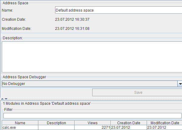
You can edit the following aspects of the address space in the address space information panel:
- Name: The name of the address space. This helps you distinguish between different address spaces of a project.
- Description: Use this field to store a longer description of the address space.
- Address Space Debugger: The debugger that is used to debug the address space. Note that only the debuggers that were configured for use in the parent project of the address space can be selected here.
Note that changes to the address space name, the address space description, and the address space debugger are not saved automatically. To save the changes, you must click on the Save button.
The lower part of the address space information panel contains a table with information about the modules inside the address space. The names and descriptions of all modules are shown in the table as well as the number of views that can be found inside the modules, the date when the modules were first created and when they were last modified.
You can modify the name and the description of each module in the table by double-clicking on the corresponding field. If that field is already selected you can just start typing the new name or the new description.
When you right-click on the table a context menu with the following menu items is shown:
- Load Module: Loads the module from the database. This option is only available if the module has not yet been loaded.
- Star Module: Stars the module. Stared modules are shown on top of the modules table.
- Search View: Shows a dialog that helps you search for views inside the module. This option is only available if exactly one module is selected.
- Resolve Imported Functions: Shows a dialog where you can forward imported functions to real functions of other modules.
- Remove Module: Removes a module from the address space. The module is not deleted from the database and can still be used in other address spaces or as a stand-alone module.
- Search: Shows a dialog that helps you search for a string in the table.
- Copy Selection: Copies the content of the selected rows to the clipboard.
Modules Nodes
Modules Nodes show you what BinNavi modules are stored in a BinNavi database. The number in the node text tells you how many modules there are.
When you select a Modules Node a table on the right side of the main window gives you basic information about the modules.
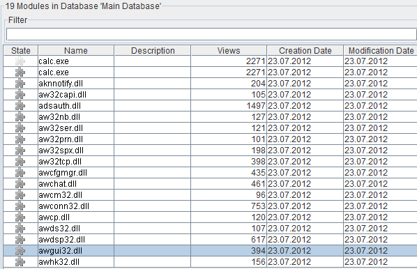
For each module in a database, the name and description of the module is shown as well as the date when the module was created and the date when the module was last modified.
You can modify the name and the description of a module in the table by double-clicking on the corresponding field. If that field is already selected you can simply start typing the new name or the new description.
You can filter the modules table by the names and descriptions of the modules. More advanced filtering options are available in the context menu of the filter field.
When you right-click on the table, a context menu is shown that provides the same options as the modules table that is shown when an address space node is selected.
Module Nodes
Module Nodes represent BinNavi modules which themselves represent disassembled files. The child nodes of a Module Node show information about all views of the module. Two numbers are part of each Module Node. The first number states how many functions there are in the module. The second number states how many custom views you have already created in the module.
When you right-click on a Module Node a context menu is shown that has the same menu items as the context menu of the Modules Nodes table. Only the table-specific menu items are omitted.
When you select a Module Node more detailed information about the module is shown on the right side of the main window.
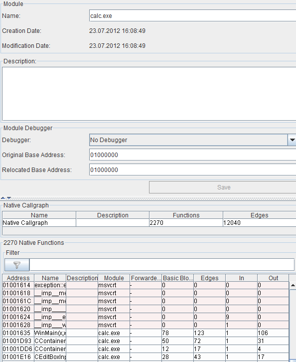
You can edit the following aspects of a module in the module information panel:
- Name: The name of the module. By default the name is set to the name of the disassembled file.
- Description: Use this to store longer descriptions about the module.
- Debugger: The debugger you want to use to debug the module. This option is only available if the module is a stand-alone module. If the module is part of an address space its debugger must be configured in the address space information panel.
- Original Base Address: The base address of the module as specified in the header of the original input file.
- Relocated Base Address: The base address of the module as it can be found in memory. In combination with the file base address this value is useful for debugging relocated modules.
Note that changes to the module name, the module description, the module debugger, the file base address, and the image base address are not saved automatically. To save the changes, you must click on the Save button.
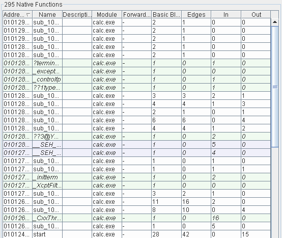
The lower part of the module information panel contains a table that shows information about the native flow graph views of the module. The start address, the name, and the description of all function views are shown in the table as well as their number of basic blocks and edges, and their indegrees (the number of functions that call a function) and outdegrees (the number of functions called by a function). For imported functions that are forwarded to other modules the forwarding information is also shown in the table.
You can modify the name and the description of each view in the table by double-clicking on the corresponding field. If that field is already selected, you can simply start typing the new name or the new description.
You can filter the views table by the names and descriptions of the views. More advanced filtering options are available in the context menu of the filter field.
When you right-click on the table a context menu is shown that provides the following options.
- Open in Last Window: Opens the view in the graph window that was last used to open a view. This option is only available if there is at least one graph window already open.
- Open in New Window: Opens the view in a new graph window.
- Open in Window ...: Lets you select in what graph window to open the view. This option is only available if there is at least one graph window already open.
- Show Derived Views: Shows a dialog that lists views that share instructions with the selected view. This is very useful to find custom views that were derived from original functions.
- Star View: Stars the view. Stared views are listed first in the table.
- Set breakpoint on function: Sets a debugger breakpoint on the start of the function.
- Copy Selection: Copies the content of the selected rows to the clipboard.
- Copy Cell: Copies the content of the cell that was clicked on to the clipboard.
- Search: Shows a dialog that helps you to search for a string in the table.
Native Callgraph Nodes
Native Callgraph Nodes are child nodes of Module Nodes. When you select a Native Callgraph Node a table is shown on the right side of the main window that gives information about the native call graph of the module.
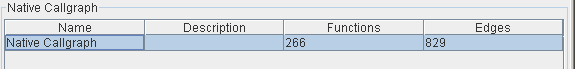
The table shows the name and the description of the native call graph as well as the number of functions and function calls in the call graph.
You can modify the description of the native call graph in the table by double-clicking on the corresponding field. If that field is already selected you can simply start typing the new description.
When you right-click on the table a context menu is shown with the same options as the context menu that is shown in the views table of the Module Nodes.
Native Flowgraph Nodes
Native Flowgraph Nodes are child nodes of Module Nodes. The number in the Flowgraph Node states how many native flow graph views belong to the module. This number equals the number of functions in the module. When you select a Native Flowgraph Node a table with information about the native flow graphs is shown on the right side of the main window.
The table that gives information about the native flow graph views is the same table as the one that is shown in the lower half of the control that is shown when a Module Node is selected. It provides the same functionality and the same context menu.
Function Nodes
The six Function Nodes Normal Functions, Library Functions, Imported Functions, Thunk Functions, Thunk Adjustor Functions, and Unknown Functions are child nodes of a Native Flowgraph Node. These nodes are used to select subsets of the all the native flow graph views of a module. For example, to see the imported functions of a module you can select the Imported Functions node.
For each of the Function Nodes, the table that gives information about the views is the same table as the one that is shown in the lower half of the control that is shown when a Module Node is selected. It provides the same functionality and the same context menu.
Module Views Nodes
The Module Views Nodes provide an overview of the custom views you have created so far.The number in each Module Views Node says how many user-created views are part of this module.
When you select a Module Views Node more detailed information is shown in three tables on the right side of the main window. There is one table for each view type (flowgraph view, callgraph view, and mixed graph view).
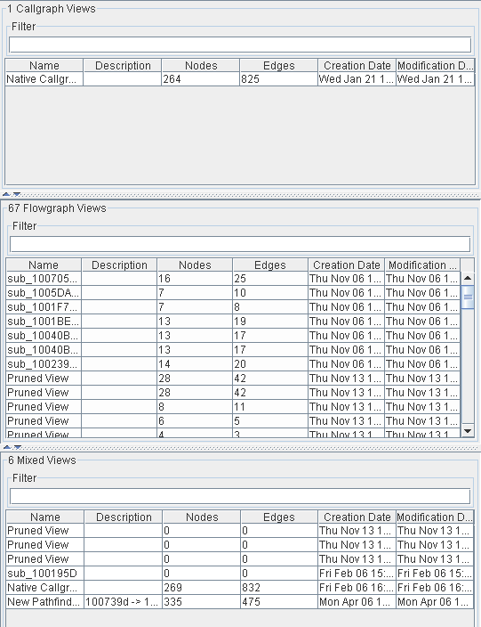
The table that gives information about the module views is the same table as the one that is shown in the lower half of the control that is shown when a Module Node is selected. It provides the same functionality and the same context menu with one exception. Since user-created views can be modified they can be deleted too. Therefore the context menu that is shown when you right-click on the table provides an additional menu for deleting a view.
Project Views Nodes
Project Views Nodes are functionally equivalent to Module Views Nodes. The difference between the two node types is that Module Views Nodes show user-created views of modules while Project Views Nodes show user-created views of projects.
Callgraph Views Nodes, Flowgraph Views Nodes, Mixed Graph Views Nodes
Callgraph Views Nodes, Flowgraph Views Nodes, and Mixed Graph Views Nodes are child nodes of the Module Views Nodes and Project Views Nodes. You can use them to filter the existing user-created views by their type. For example a click on Callgraph Views Nodes changes the right side of the main window to a single table that shows only the user-created call graph views of a module/project.
The table that gives information about the views of each type is the same table as the one that is shown when a Module/Project Views Node is selected. It provides the same functionality and the same context menu.
Tagged Views Nodes
Tagged Views Nodes tell you about the views you have previously tagged. When you select a Tagged Views Node a table with information about the tagged views is shown on the right side of the main window.
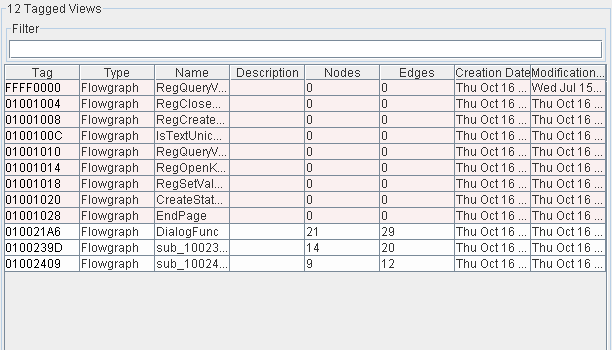
The table that gives information about the tagged views equals the table that is shown in the lower half of the control that is shown when a Module Node is selected. It provides the same functionality and the same context menu with one exception. For each tagged view the tag that is used to tag the view is shown in the first column of the table.
Tagged Views Nodes have child nodes for each used tag. Using these child nodes it is possible to filter the table shown on the right side of the main window. If you select a child node only those views that are tagged with that tag are shown in the table on the right side of the main window.
Node-tagged Views Nodes
Node-tagged views nodes are similar to tagged views nodes. Instead of telling you the tagged views they tell you which views contain nodes tagged with node tags. This helps you quickly find exactly those views whose nodes you have previously tagged.
Debug Traces Nodes
Debug Traces Nodes provide quick access to the previously recorded debug traces of a module. The number at a Debug Traces node specifies the number of available debug traces.
When a Debug Traces node is selected, the right side of the main window changes to the control shown below.
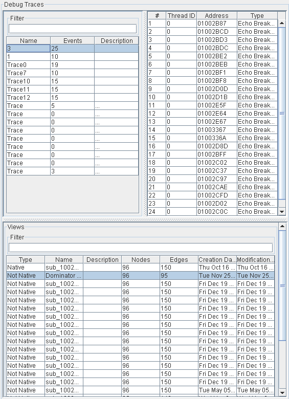
At the top left side of the control, you can select the debug trace you want to view. At the top right side the debug events of the selected trace are shown. At the bottom, all views of the module which contain nodes that were hit by the currently selected trace are shown. This helps you quickly find the views which are useful to analyze in combination with the selected trace.
Data Nodes
Data nodes provide an option to view the complete binary data of modules in a hex view component. The right Load button is used to load binary data from a file. The Store button then writes the data from the file to the database. From that point on, the stored binary data is associated with the module and can be loaded from the database again using the left Load button.
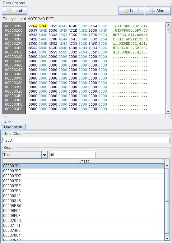
It is possible to navigate through the binary data by jumping to offsets or by searching for data.
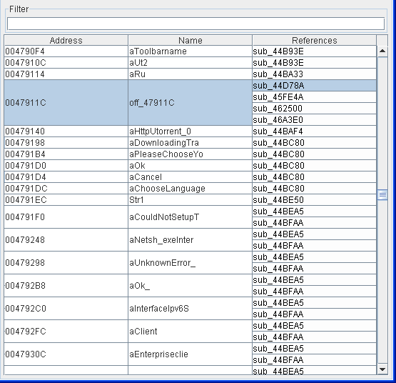
Global Variable Nodes
The Global Variable Nodes provide an overview of all the global variables that were recognized in the module. You can use this view to see what functions reference which global variables and you can change the names of global variables here.
Debuggers Nodes
The Debuggers Node is the parent node of all pre-configured debuggers that can be used in BinNavi. The number that is part of each Debuggers Node states how many debuggers were already configured.
When you right-click on a Debuggers Node a context menu pops up that offers the following options.
- Create Debugger: Creates a new debugger with standard options.
When a Debuggers Node is selected, a table that gives information about the configured debuggers is shown on the right side of the main window.
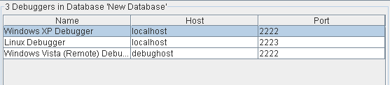
It is possible to modify all fields of the table by double-clicking on them. If the field is already selected, it is also possible to simply start typing the value for that field.
When you right-click on the table, a context menu is shown which provides the following options:
- Delete Debugger: Deletes the debugger configuration from the database
- Copy Selection: Copies the content of the selected rows to the clipboard.
Debugger Nodes
A debugger node represents the configuration of a single debugger that can be used to debug BinNavi modules and projects.
When you right-click on a Debugger Node a context menu is shown that provides the same options as the context menu of the Debuggers Nodes table.
When a Debugger Node is selected, more information about the debugger is shown on the right side of the main window.
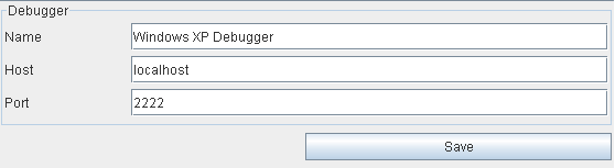
In the debugger information panel you can edit the following aspects of a debugger.
- Name: The name of the debugger.
- Host: Location of the debug client.
- Port: Port used to connect to the debug client.
Note that changes to the debugger settings are not saved automatically. To save the changes, you must click on the Save button.
View Tags Nodes
View Tags Nodes are the parent nodes of all tag nodes of a database. They are the starting point for creating new view tags and managing existing view tags. The number that is part of each View Tags Node states the number of view tags stored in the database.
When a user right-clicks on a View Tags Node, a context menu is shown that provides the following options.
- Create Root Tag: Creates a new view tag with default values.
When a View Tags Node is selected, a table that provides information about the existing view tags is shown on the right side of the main window.
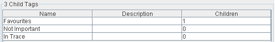
In this table the following information is shown about each tag:
- Name: The name of the tag.
- Description: The description of the tag.
- Children: Number of child-tags of this tag.
It is possible to modify the tag name and the tag description of the table by double-clicking on them. If the field is already selected, it is also possible to simply start typing the value for that field.
View Tag Nodes
Each View Tag Node represents a single view tag that can be used to store views in the database. The number that is part of each view tag node states the number of child tags of a tag.
When you right-click on a View Tag Node, a context menu is shown that provides the following options.
- Append Tag: Creates a new tag as child of the selected tag.
- Insert Tag: Creates a new tag between the selected tag and its children.
- Delete Tag: Deletes the view tag from the database.
- Delete Subtree: Deletes the view tag and all child tags of the tag from the database.
When a Tag Node is selected, more information about the corresponding tag is shown on the right side of the main window.
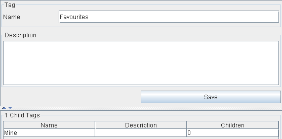
In the tag information panel you can edit the following aspects of a tag.
- Name: The name of the tag.
- Description: The description of the tag.
Note that changes to the tag settings are not saved automatically. To save the changes, you must click on the Save button.
In the lower half of the tag information panel, a table is shown that provides information about the child tags of the tag. This table is functionally equivalent to the tags information table that is shown on the right side of the main window when a View Tags Node is selected.
Hotkeys
Except for the hotkeys that are made available through the main menu and the context menus, there are no additional hotkeys available in the main window. However are a few drag & drop operations available which are very useful.
- Copy a module view: To create a copy of a module view, drag a view from a views table onto the Module Views node.
- Convert a module view to a project view: To create a copy of a module view as a project view drag the module view you want to copy from the views table onto the Project Views node.
- Tag a view: To tag a view drag the view from a views table onto the tag node in the tree.
- Add a module to an address space: To add a module to an address space, drag the module from a table or from the tree onto the node of the address space.